








How to use a laser cutting machine for sheet metal, load the correct stock, import and check the DXF, select a cutting process, then verify the job on the table before cutting. Start with one part. If it separates fully and meets the drawing’s dimensions and edge requirements, release the rest of the nest for production.
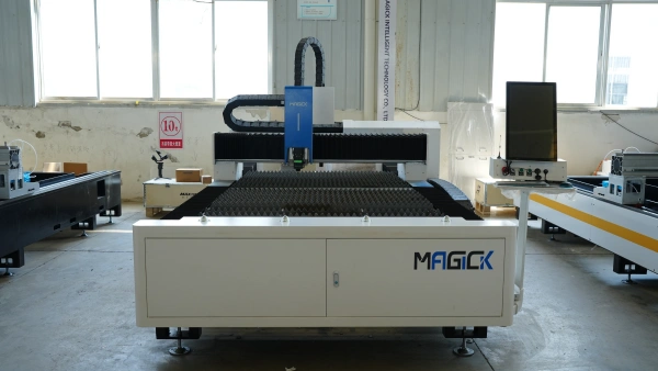
This laser cutting workflow applies to MAGICK flatbed machines, such as the open-style single-table MK-S, the interchangeable-table MK-E, and the fully enclosed MK-P. The examples below illustrate how settings may vary depending on the table layout, controller, or material. Please refer to the user manual and on-site operating procedures for your specific machine when performing these operations.
1. Check the Machine and Load the Sheet
Confirm that the chiller, fume extraction, assist gas, and protective systems are ready under your pre-start procedure. Inspect the bed for offcuts that could lift the sheet or enter the cutting head’s path. Confirm the sheet grade, thickness, and surface condition against the job sheet before completing the machine’s homing procedure.
- MK-S single table. Check that the sheet is fully supported and that the loaded position leaves room for the complete nest. Plan unloading around the single worktable.
- MK-E exchange table. After an exchange, verify that the active pallet is in position and that the program origin matches the new sheet. The next sheet can be staged at the loading station using the machine’s approved procedure.
- MK-P enclosed table. Check the door and interlock status before enabling the cut. Use the machine’s designated viewing arrangement to monitor the job.
Compare MAGICK sheet metal laser cutting machines
2. Import the DXF and Check the Cut Order
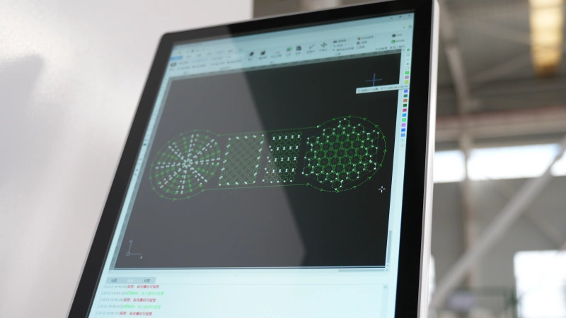
After importing the DXF, measure one known dimension on screen. If a bracket is drawn 100 mm wide, confirm that the imported width is 100 mm before nesting. Check for duplicate lines, open contours, and construction lines that could create an unintended cut.
For a bracket with mounting holes, schedule the holes before the outside contour so the part stays supported while the holes are cut. Check that the lead-ins enter from the scrap side and fit inside small internal features. Verify that kerf compensation is applied on the intended side of each contour. A wrong outside dimension and an undersized hole can point to a compensation problem even when the DXF scale is correct.
3. Match the Process to the Material, Gas, and Nozzle
Start with the approved process for the machine’s laser power, material grade, thickness, and assist gas. Cross-check the preset against the nozzle installed on the head. Review cutting speed, gas pressure, and piercing settings together. Check the focus position and nozzle-to-sheet gap separately because they control different parts of the setup.
For example, a carbon steel part cut with oxygen may need its edge prepared before coating, depending on the finish requirement. If a stainless steel panel needs a bright edge with minimal oxidation, confirm the approved nitrogen process and check the finished edge against the order. A gas change requires its own process and trial cut. Read MAGICK’s guide to laser cutting steel sheet.
4. Set the Origin, Frame the Job, and Dry Run
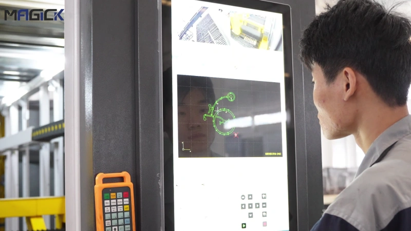
A toolpath can fit the drawing and still run off the physical sheet. Set the work origin against the loaded stock, then use the controller checks in sequence.
| Check | What to look for |
|---|---|
| Toolpath preview | The inner features cut first, and the head follows the intended sequence. |
| Frame or boundary check | The nest footprint stays within the usable sheet, including on a remnant or a newly exchanged pallet. |
| Dry run | Where supported, the head follows the programmed path with the cutting beam disabled. Watch for an unexpected move or an obstacle in the work area. |
The exact controls depend on the installed system. BOCHU documents Frame and Dry Run as separate functions in its CypCut user manual.
5. Test Cut and Approve the First Part
When performing a laser test cut, use material of the same type and thickness. The test cut should include areas where problems are most likely to occur during actual cutting, such as the smallest holes or tight corners. Once the laser cutting machine has reached a safe operating state, check whether the workpiece has been completely ejected from the mold and inspect the bottom surface for burrs and slag, then measure the critical dimensions. For thick plates, also check for taper.
MAGICK 60 kW Carbon Steel Thickness Test Cutting Log
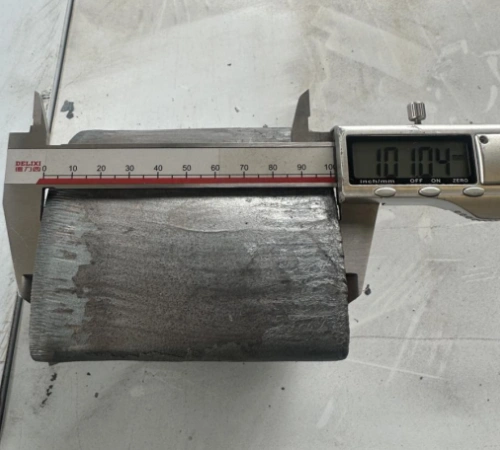
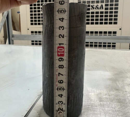
In August 2025, MAGICK’s R&D department conducted test cuts on carbon steel using a 60-kilowatt sheet metal laser cutting machine equipped with the BOCHU FSCUT8000 control system and 99.999% auxiliary oxygen. The table below lists the test parameters and conclusions.
| Nominal thickness | Edge criteria or observation in the report | Recorded verdict |
|---|---|---|
| 60 mm | Smooth cut face, no burrs, no dross | Pass |
| 80 mm | Smooth cut face, no burrs, no dross | Pass |
| 100 mm | Smooth cut face, no burrs, no dross | Pass |
| 160 mm | Slightly rough cut face, no burrs, slight bottom dross | Pass |
The report placed the approximate cut-through limit for this setup at 160 mm and flagged plate quality as especially important above 80 mm. For a job that requires a clean underside, the 160 mm sample would still need to be checked against the customer’s finish requirement. The engineers also noted that positive focus could be used below 60 mm on this setup and recommended negative focus above 60 mm. The report gives no focus offsets, cut speeds, or repeat-run data.
6. Run the Batch and Check for Process Changes
Save the confirmed machining tasks and processes, and then monitor the cutting process in accordance with the machine tool manual and on-site procedures. If an alarm occurs, or if there is suspected tool-workpiece contact or an inability to engage the cut, stop machining according to the prescribed procedures. Before changing any settings, compare the newly discovered defects with the first workpiece that met the standards.
| Symptom | First checks |
|---|---|
| The first part is off-size | Verify DXF , imported dimensions, and kerf compensation. |
| The holes fail but the outline cuts through | Check the entry holes, through holes, and feature settings in the confirmed process. |
| Corners show burn marks | Check the feed rate settings and the controller’s angle settings for this cutting task. |
| Dross appears after several acceptable parts | Check the nozzle for spatter or damage, the sheet metal for warping, and the gas supply for any reduction. |
| The path is offset after a pallet exchange | Before machining the frame again, please verify the currently selected pallet, the position of the sheet material, and the work origin. |
After laser cutting is complete, shut down the machine and record the cutting parameters, material, and cutting data for the first sample that has been verified as passed. This will provide the next operator with specific setup instructions, reducing the need for verification during repeat orders and saving time.
Request a Sample Cut
For a sample on a MAGICK fiber laser cutting machine, send your DXF, material grade, and thickness. Mark the tightest tolerance and tell us whether the part goes straight to welding, coating, or assembly. Those details define what the sample needs to demonstrate. Request a sample cut from MAGICK.