








Indeed, a laser system designed for industrial use can successfully make cuts in aluminum sheets. However, there is more to it than simply cutting the aluminum. One also has to consider the quality, time, and cost of cutting each part produced by the machine. There are numerous factors that influence the decision being made regarding a particular type of aluminum. They include the kind of alloy being used, its state before pre-cutting, thickness, surface state, geometry of the part, as well as the assistance of the gas and optical systems used by the machine.
For manufacturers, fiber laser cutting aluminum can produce profiles, holes, slots, and nested parts directly from a digital drawing. However, a straight cut through a thick sample proves only separation capability. It does not prove that the same setup can reliably pierce the material, cut small internal features, protect cosmetic surfaces, and deliver parts ready for bending, welding, anodizing, or assembly.
This guide provides a detailed overview of how to evaluate aluminum cutting processes, covering everything from material properties and shielding gases to cut edge quality and machine tool selection. In addition, it offers a practical test-cut checklist to facilitate a data-driven comparison of suppliers.
Can You Laser Cut Aluminum?
When the whole system is tailored to the needs of the application, industrial fiber lasers are able to cut aluminum sheets and plates. IPG Photonics points out that materials that exhibit a high infrared reflectance capacity, such as aluminum, can be processed using lasers producing near-infrared wavelengths, provided that enough power density is provided. Thus reflectivity must be taken into account both in terms of the processing technology and the design of the tools involved.[1]
However, the word “fiber laser” refers to different systems of equipment. A marking machine which is designed to make surface modifications must not be classified the same way as a machine designed to make a sheet cut. Make sure that every relevant element of the cutting apparatus is suitable for the task, including the laser source, the cutting head, optics, optics protection system, gas equipment, electronic system and control tools.
The specification of the material is equally important and just saying “aluminum” is not enough to fulfill the requirements of the production process. There is a need to conduct a proper trial to evaluate:
- the alloy and temper;
- the nominal and measured thickness;
- whether the surface is bare, anodized, painted, laminated, or protected by film;
- which face is cosmetic;
- the drawing revision and units;
- critical dimensions and edge requirements;
- what happens after cutting.
A successful demonstration on one alloy and thickness does not establish the same capability for every aluminum job. Send the supplier the actual stock specification and representative drawing before comparing machines.
How Fiber Laser Cutting Aluminum Works
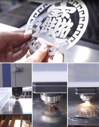
When cutting aluminum with laser energy, the cutting head focuses the beam onto a small area of the material. The aluminum heats and melts, while assist gas flows through the nozzle and expels molten material from the kerf. CNC motion guides the cutting head along programmed contours to separate the part from the surrounding sheet.
In nitrogen-assisted fusion cutting, the laser provides the necessary energy to melt the material. On the other hand, the inert gas is responsible for removing the molten material and insulating the high-temperature cutting zone from the surrounding atmosphere. Unlike in oxygen-assisted cutting where heat is generated by the oxidation process, TRUMPF identifies nitrogen and argon as inert cutting gases used in fusion cutting where the energy required for cutting comes from the laser. [2]
The production program controls not only the movement of contours but also determines the piercing sequence, selection of entry points, and corner handling. Knowing this information is important since a set of small brackets may need different piercing procedures and more possible maneuvers than a larger plate with a simple outline. It is also obvious that linear speed cannot give a complete picture of the processing task.
A high contour speed has limited value if piercing, loading, sorting, cleaning, or the next manufacturing operation controls the overall output. For a closer explanation of beam focusing and material interaction, see MAGICK’s guide to how a laser cutter works.
Why Aluminum Is Challenging to Laser Cut
Reflectivity and Equipment Compatibility
Aluminum reflects laser energy, so the suitability of the laser source and optical system is critical. TWI explains that reflected energy may be reflected back through the optical path, potentially causing damage to an unsuitable system. The organization recommends confirming with the laser supplier whether the equipment is specifically designed for aluminum processing and equipped with appropriate back-reflection protection measures. [3]
Ask how the configuration specified in the quote handles reflected energy and which aluminum processing applications it supports. A general statement that the equipment “can cut metal” is insufficient. The response should address the complete system as proposed, including the laser source, cutting head, optical system, control system, and safety features.
Thermal Conductivity
Aluminum rapidly conducts heat away from the cutting area. This property, combined with its reflectivity, influences how energy must be transferred to establish and maintain a stable cut. TRUMPF considers high thermal conductivity and high reflectivity to be the core challenges of laser processing aluminum. [4]
Therefore, representative tests should not be limited to long, straight contours. Corners, holes, closely spaced features, narrow areas, and other geometries similar to production parts should be used. These features provide a more comprehensive reflection of process stability and heat distribution. If flatness is critical for bending, assembly, or machining, inspect the workpiece after it has cooled and been removed from the support table.
Surface Condition and Cosmetic Requirements
Record whether the stock is bare, anodized, painted, laminated, or protected by film. Coatings and film add variables to a process developed for the base material. Confirm their compatibility with the machine supplier before assuming that one cutting program can be used without adjustment.
When manufacturers laser cut aluminum sheet for visible panels, they should define which face is cosmetic before the trial. A dimensionally correct part may still be unacceptable if handling, support contact, spatter, or film damage marks the visible surface. Include surface appearance in the acceptance criteria rather than reviewing it after the machine configuration has already been selected.
Aluminum Alloys, Thickness, and Laser Power
Reference Cutting Parameters for 12 kW Aluminum Alloy
The following parameters provide a starting reference for cutting aluminum alloy with a 12 kW fiber laser system. They should not be treated as universal settings or guaranteed production results. Actual cutting performance depends on the alloy and temper, material condition, machine model, laser source, cutting head, nozzle design, nitrogen purity, focus position, and the required edge quality.
| Material | Thickness (mm) |
Reference Cutting Speed (m/min) |
Laser Power (W) |
Assist Gas | Gas Pressure (bar) |
Nozzle |
|---|---|---|---|---|---|---|
| Aluminum Alloy | 1 | 50–60 | 12,000 | N2 | 12 | 2.0S |
| Aluminum Alloy | 2 | 35–40 | 12,000 | N2 | 12 | 2.0S |
| Aluminum Alloy | 3 | 30–35 | 12,000 | N2 | 12 | 2.0S |
| Aluminum Alloy | 4 | 25–30 | 12,000 | N2 | 12 | 2.0S |
| Aluminum Alloy | 5 | 20–25 | 12,000 | N2 | 14 | 2.5S |
| Aluminum Alloy | 6 | 14–18 | 12,000 | N2 | 14 | 2.5S |
| Aluminum Alloy | 8 | 7–9 | 12,000 | N2 | 14 | 2.5S |
| Aluminum Alloy | 10 | 5–7 | 12,000 | N2 | 14 | 5.0B |
| Aluminum Alloy | 12 | 3–4 | 12,000 | N2 | 16 | 5.0B |
| Aluminum Alloy | 14 | 1.8–2.8 | 12,000 | N2 | 16 | 5.0B |
| Aluminum Alloy | 16 | 1.5–1.8 | 12,000 | N2 | 16 | 5.0B |
| Aluminum Alloy | 18 | 1–1.5 | 12,000 | N2 | 16 | 5.0B |
| Aluminum Alloy | 20 | 0.8–1.2 | 12,000 | N2 | 16 | 5.0B |
| Aluminum Alloy | 25 | 0.5–0.7 | 12,000 | N2 | 16 | 6.0B |
| Aluminum Alloy | 30 | 0.25–0.3 | 12,000 | N2 | 18 | 7.0B |
| Aluminum Alloy | 40 | 0.15–0.2 | 12,000 | N2 | 18 | 7.0B |
Start With the Correct Alloy and Temper
Alloy and temper influence the intended use of the component and the operations that follow cutting. Two common examples are 5052 and 6061. Hydro describes 5052 as a non-heat-treatable alloy with magnesium as its main alloying element and notes that it is commonly used in sheet and plate form. Hydro describes 6061 as an aluminum-magnesium-silicon alloy available in several tempers, including 6061-O, 6061-T4, 6061-T6, and 6061-T651. [5, 6]
| Material example | What to specify | What to evaluate in the trial |
|---|---|---|
| 5052 sheet | Full grade and temper, thickness, surface condition | Cut edge, holes, cosmetic face, and intended bending or finishing operation |
| 6061 sheet or plate | Full grade and temper, thickness, drawing revision | Critical dimensions, edge condition, flatness, and any machining allowance required afterward |
First, select the alloy required for the finished part, and then develop a cutting process based on those specifications. Never substitute an alloy grade simply because a demonstration sample is easier to cut. If the part requires bending, welding, machining, or anodizing, involve the teams responsible for those processes when reviewing the sample.
Hydro’s reference materials support the material descriptions provided above; they are not laser cutting parameter tables. No inferences regarding cutting speeds, maximum thicknesses, or the processing capabilities of MAGICK machines should be drawn from them.
Separate Cutting Through From Production Capability
Laser power is an important selection factor, but it does not define a universal aluminum thickness limit. Practical capacity also depends on the beam and optical configuration, cutting head, nozzle, gas delivery, alloy, temper, geometry, surface condition, and required edge quality.
Separate four different questions:
| Capability | What it proves |
|---|---|
| Maximum piercing thickness | The system can establish a starting point through the material under stated conditions |
| Maximum separation thickness | The system can cut through and separate a simple profile |
| Repeatable production thickness | Complete parts can be produced repeatedly with acceptable dimensions and edges |
| Stable daily production range | The process can maintain the required output, quality, handling, and cost during normal production |
Maximum thickness specifications typically do not answer certain key questions. Can the equipment reliably punch holes at that thickness? Can the required holes, slots, and corners be machined? How long does the entire machining cycle take? Is edge cleaning required before welding or assembly? What is the consistency among multiple parts in the same layout?
This article does not provide a universal power-to-thickness chart because useful production limits must explicitly specify the alloy, condition, gas, equipment configuration, geometry, and acceptable edge condition. Where MAGICK test data is available, it should be presented in conjunction with the above conditions, rather than as a universal rating applicable to all aluminum processing tasks.
For U.S. drawings and material orders, please retain the specified units. For example, 1/4 inch equals 6.35 millimeters; therefore, a test conducted on 6-millimeter-thick material does not represent the same nominal thickness. When requesting a test weld, please provide accurate purchasing specifications.

Nitrogen vs. Compressed Air for Aluminum Cutting
Nitrogen is commonly used when limiting oxidation is important. Compressed air is also used for aluminum on suitably configured systems, but its oxygen content can affect the cut surface. The appropriate choice depends on the alloy, thickness, machine configuration, gas supply, edge acceptance, downstream operation, and total cost. [2, 7]
| Decision factor | Nitrogen | Compressed air |
|---|---|---|
| Cut surface | Limits oxidation during cutting; still requires inspection | Can produce mild oxidation; verify downstream compatibility |
| Supply planning | Check purity, pressure, flow, and supply capacity | Check pressure, flow, dryness, filtration, and compressor capacity |
| Cost comparison | Include purchased gas or generation, storage, and delivery | Include compressor power, treatment equipment, maintenance, and capacity |
| Acceptance test | Inspect dross, dimensions, appearance, and downstream results | Apply the same acceptance criteria using the actual air system |
A decision should not be based solely on appearance. Samples must also meet dimensional requirements and perform well during welding, coating, anodizing, or assembly. Using nitrogen does not necessarily guarantee burr-free edges, and just because a factory has a compressor does not mean compressed air is free.
Bystronic discussed the use of high-pressure shop compressed air in aluminum processing and noted that slight oxidation may occur. The company also emphasized the importance of evaluating subsequent processes to avoid incurring greater costs later on due to gas savings.[7] In another discussion, Bystronic explained that molten material may cool and reattach near the bottom of the cut, and that in certain applications, using alternative gas mixtures can mitigate this effect. These results vary by process and are not a one-size-fits-all solution. [8]
If both nitrogen and compressed air are available, comparative tests should be conducted using appropriate parameters for each under identical conditions regarding alloy, condition, thickness, and drawing specifications. Record the complete cycle time, gas or air system requirements, the number of合格 parts, and any deburring or cleaning processes. The optimal process is the one capable of producing the required parts at the lowest defined total cost—not necessarily the one with the lowest gas costs.
How to Evaluate Edge Quality and Reduce Rework
A useful inspection begins with the part’s function. A visible enclosure panel may require a clean cosmetic face and consistent edge, while an internal mounting plate may be judged mainly by fit, hole position, and readiness for assembly. Translate those requirements into checks that both the buyer and supplier can repeat.
Inspect the top edge, bottom edge, cut face, corners, holes, and narrow features. Relevant observations include:
- attached dross on the lower edge;
- variation in cut-face texture;
- differences between the top and bottom of a feature;
- corner damage or heat accumulation;
- hole roundness and small-feature integrity;
- top-surface marks, spatter, or film damage;
- flatness after cooling;
- cleaning required before the next operation.
After the parts have cooled, critical dimensions should be measured according to the agreed-upon method and based on the correct drawing revision. The machine tool’s positioning specifications describe the motion system under specified conditions; they should not be interpreted directly as a general guarantee of every feature of the finished product.
When cutting results require improvement, start with the process parameters validated by the manufacturer. Work with the supplier to check the nozzle condition and alignment, focus, gas delivery, cutting speed, and material condition. Change only one variable at a time, and document each sample along with its corresponding setting parameters. This provides a traceable basis for subsequent testing, rather than relying on memory or photographs.
If the parts to be produced are expected to be delivered directly to the assembly line, do not evaluate only polished demonstration samples. Inspect the cut edges and document any necessary post-processing steps, such as deburring, cleaning, or surface treatment. If secondary processing is permitted, incorporate it into production planning and cost accounting.
How to Choose an Aluminum Laser Cutting Machine
Match the Configuration to the Workload
The right fiber laser for cutting aluminum is the one that meets the production requirement under repeatable conditions. Start with a small set of representative drawings rather than choosing power from a maximum-thickness table alone.
Include at least:
- the alloy and thickness used most frequently;
- the thickest recurring aluminum job;
- a part with demanding holes, slots, corners, or cosmetic requirements;
- expected quantities and accepted parts per shift or week;
- downstream operations and their edge or surface requirements.
Just ask for a quote and test order on those jobs. Include sheet dimensions, alloys and tempering, quantity, critical dimensions, cosmetic surfaces, and edge condition required. If aluminum shares the workload schedule with carbon, stainless steel, copper, or brass, give an approximate mix and changeover expectations.
Include Handling and Facility Requirements
Loading, unloading, sorting, and remnant management can occupy a substantial part of the working cycle. Compare table arrangements alongside cutting performance, especially for repeated batches. Check how full sheets enter the cell, how finished parts are separated and sorted, and whether the next operation can absorb the planned output.
Also confirm:
- electrical supply and power quality;
- chiller and environmental requirements;
- nitrogen or compressed-air capacity;
- extraction and filtration;
- floor space, access, and foundation requirements;
- installation and commissioning responsibilities;
- operator and programmer training;
- warranty, troubleshooting, consumables, and spare-parts support.
MAGICK offers metal sheet fiber laser cutting machines with different table and enclosure arrangements. Aluminum capability must be confirmed for the specific laser source, cutting head, optical protection, gas system, and process package included in the quotation.

Compare the Cost of Accepted Parts
Evaluate purchase price alongside the cost of running representative jobs. Include material utilization, setup, piercing, contour cutting, loading, unloading, gas or compressed air, consumables, inspection, rejected parts, and secondary operations.
A useful comparison is:
Total defined job cost ÷ number of accepted parts = cost per accepted part
List what the calculation includes so that another supplier or internal production team can reproduce it. Keep rework and rejected parts visible instead of hiding them in an optimistic throughput estimate.
The correct aluminum laser cutting machine should reduce the time or cost needed to produce acceptable parts across the real production mix. Extra cutting speed has limited value if unloading, sorting, bending, welding, or inspection remains the bottleneck.
What to Include in an Aluminum Cutting Trial
A documented cutting trial converts a sales demonstration into comparable production evidence. Give each supplier the same material specification, drawing revision, acceptance criteria, and cost boundary.
| Trial item | What to document |
|---|---|
| Material | Alloy, temper, nominal and measured thickness, surface condition, coating or film |
| Geometry | Holes, slots, corners, long contours, narrow sections, and critical dimensions |
| Machine | Model, laser power, source, cutting head, optical protection, and table arrangement |
| Assist gas | Gas type, purity or specification, pressure, supply method, and consumption where measurable |
| Process time | Loading, positioning, piercing, contour cutting, unloading, sorting, and complete cycle |
| Inspection | Dimensions, holes, dross, cut-face condition, corners, flatness, and cosmetic surfaces |
| Secondary work | Deburring, cleaning, machining allowance, welding preparation, or anodizing preparation |
| Repeatability | Several parts across a representative nest or repeated cycle—not one selected sample |
| Acceptance | Drawing revision, measurement method, approved edge condition, and responsible reviewer |
Keep the cutting file, parameter record, gas information, photographs, inspection results, and cycle-time video together. If the trial succeeds, these records provide a baseline for commissioning and prevent production from starting with a different drawing or material specification.
Frequently Asked Questions
Can a Fiber Laser Cut Thick Aluminum Plate?
Suitable industrial systems can cut aluminum plate, but the practical thickness range varies with alloy, temper, machine configuration, assist gas, geometry, required edge quality, and production rate. Request a trial at the actual thickness using representative internal features and the complete cutting cycle. A maximum-thickness straight cut is not a production specification.
Is Nitrogen Always Better Than Compressed Air?
No. Nitrogen is useful when limiting oxidation is important, while compressed air can be appropriate when its resulting edge condition is acceptable. Compare dimensions, dross, surface condition, downstream processing, supply requirements, and total cost on the same material and drawing before selecting the process.
Can You Laser Cut Anodized Aluminum?
The specific stock and equipment must be evaluated. Cutting through an anodized sheet exposes a new edge that does not have the original anodized layer. If appearance or corrosion protection must be consistent across the complete component, determine whether anodizing should take place after cutting and fabrication.
Does More Laser Power Always Produce a Better Cut?
No. Power must work with the source, optics, cutting head, nozzle, gas delivery, motion system, material, and validated process settings. Judge the proposed configuration by representative finished parts, repeatability, complete cycle time, and cost per accepted part rather than treating output power as a quality rating.
What Should I Send for an Aluminum Cutting Machine Quote?
Please provide the alloy type and heat treatment condition, thickness distribution, sheet dimensions, estimated quantity, representative CAD drawings, critical dimensions, appearance requirements, and subsequent processes (such as bending, welding, machining, or anodizing). Please also provide information on the facility and gas systems so that the proposal can cover installation and production—not just the cutting machine itself.
Prepare for a Useful Machine Comparison
Successful fiber laser cutting aluminum requires the machine, material, optical protection, assist gas, programming, handling, inspection, and downstream operations to work as one production system. The most reliable comparison uses representative parts, documented conditions, repeatability, complete cycle time, and cost per accepted part.
The right fiber laser for cutting aluminum should be selected from those results—not from laser power or a maximum-thickness claim alone. To discuss a MAGICK configuration, prepare the material specifications, thickness distribution, sheet dimensions, quantities, drawings, critical tolerances, surface requirements, and available utilities. These details provide the basis for selecting a machine and defining a useful aluminum cutting trial.
Ask each supplier to document what was tested, what was measured, and what work remained after cutting. Compare the same drawings and acceptance criteria, retain the resulting samples, and record any differences between demonstration conditions and the proposed production installation. This makes the final quotation easier to evaluate and gives commissioning teams a traceable starting point if the machine is purchased.
Sources and Further Reading
The references below support the general explanations of laser behavior, fusion cutting, aluminum reflectivity, material properties, assist gases, and the MAGICK product range. They do not constitute measured MAGICK performance data. Actual thickness, speed, edge condition, gas consumption, and cost must be verified for the quoted configuration and production requirement.
[1] IPG Photonics — Fiber Lasers 101
[3] TWI — Overcoming the Problems with Laser Cutting of Aluminium
[4] TRUMPF — Laser Community, Issue 21 (2015)
[8] Bystronic — High-Powered Lasers and the Evolution of Assist Gases
