








You copy a cutting table, enter the speed and focus, and run the first part. Slag still clings to the bottom edge. Small holes need cleanup. A setting that worked yesterday gives a different result on the next batch of plate.
That gets frustrating quickly. Every trial uses material, and every extra minute of grinding pushes the order further from the delivery schedule.
Useful 12kW fiber laser cutting parameters connect a complete set of settings to a particular machine configuration and material. The charts below provide reference entries for carbon steel, stainless steel and aluminum, followed by a practical way to investigate poor cuts and turn a trial into a repeatable job.
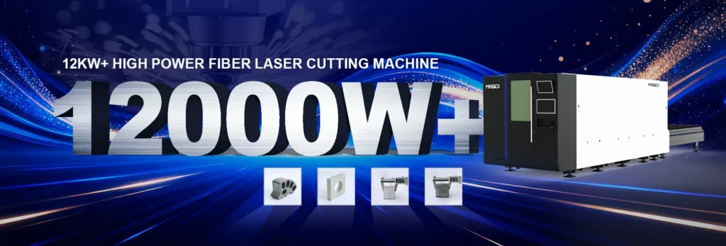
| Mã sản phẩm. | MK-3015G | MK-4020G | MK-6020G | MK-6025G | MK-8025G | MK-10250G |
|---|---|---|---|---|---|---|
| Khu vực làm việc | 3000 × 1500 mm | 4000 × 2000 mm | 6000 × 2000 mm | 6000 × 2500 mm | 8000 × 2500 mm | 10200 × 2500 mm |
| Công suất đầu ra của tia laser | 12000W / 20000W / 30000W / 40000W / 50000W / 60000W / 80000W | |||||
| Độ chính xác khi định vị lại nhiều lần | ±0,03 mm | |||||
| Độ chính xác định vị | +0.02 mm | |||||
| Tốc độ tối đa | 120 m/min | |||||
| Gia tốc tối đa | 1,5G | |||||
12kW Laser Cutting Parameters by Material and Thickness
Before selecting a row, match the reference configuration to your equipment.
| Reference detail | Configuration covered here |
|---|---|
| Laser source | RFL-12000S(100u), the 100μm variant |
| Optical configuration | 100 mm collimating / 200 mm focusing |
| Materials | Carbon steel, stainless steel and aluminum alloy |
| Data status | Selected reference entries; not MAGICK production-validation results |
| Trial-only entries | Red-marked trial entries in the source workbook are excluded |
The source does not identify the exact material grades, cutting-head model, gas purity, pressure measurement point or focus-zero convention. These details need confirmation against the machine’s process documentation before the values are applied.
Nozzle codes and signed focus values are retained from the source. Match the nozzle designation and focus convention to the actual head and controller. The tables show selected thicknesses, not a guaranteed production range or the machine’s maximum cutting capacity.
12kW Carbon Steel Cutting Parameters
| Thickness (mm) | Speed (m/min) | Power (W) | Gas | Pressure (bar) | Nozzle code | Focus (mm) | Height (mm) |
|---|---|---|---|---|---|---|---|
| 3 | 30–35 | 12000 | N₂/Air | 13 | 2.0S | 0 | 0.5 |
| 6 | 10–13 | 12000 | N₂/Air | 13 | 2.5S | 0 | 0.5 |
| 10 | 6–7 | 12000 | N₂/Air | 13 | 4.0S | −3 | 0.5 |
| 10 | 2–2.3 | 7000 | O₂ | 0.6 | 1.2E | +8 | 0.8 |
| 16 | 1.4–1.6 | 9500 | O₂ | 0.6 | 1.4E | +11 | 0.8 |
| 20 | 1.2–1.4 | 12000 | O₂ | 0.6 | 1.6E | +11 | 0.8 |
The oxygen rows above come from the source’s positive-focus process block. They should remain complete combinations; do not combine their speed or nozzle with values taken from a different process.
For 10 mm carbon steel, the table contains both an N₂/Air entry and an oxygen entry. Their power, pressure, nozzle and focus differ. Treat each as a separate reference process to evaluate against the required edge and subsequent operations.
The source groups nitrogen and air in some entries. That does not establish identical oxidation, appearance or finishing requirements with both gases.
For parts that move into welding, painting or assembly, include the required edge preparation when assessing cắt laser thép cacbon.
12kW Stainless Steel Cutting Parameters
| Thickness (mm) | Speed (m/min) | Power (W) | Gas | Pressure (bar) | Nozzle code | Focus (mm) | Height (mm) |
|---|---|---|---|---|---|---|---|
| 3 | 30–35 | 12000 | N₂ | 13 | 2.0S | 0 | 0.5 |
| 6 | 13–15 | 12000 | N₂ | 8 | 3.5B | 0 | 0.5 |
| 10 | 6.5–7.5 | 12000 | N₂ | 5 | 5.0B | −1 | 0.5 |
| 12 | 5–5.5 | 12000 | N₂ | 6 | 6.0B | −4 | 0.5 |
| 16 | 2–2.3 | 12000 | N₂ | 6 | 7.0B | −8 | 0.3 |
| 20 | 1.2–1.4 | 12000 | N₂ | 6 | 7.0B | −11 | 0.3 |
Define what an acceptable edge means before the trial. A visible component may have different discoloration and finishing requirements from a concealed bracket.
Inspect the underside as well as the exposed cut face. A part that needs extended deburring can hold up the next operation even when it separates cleanly from the sheet. Use your actual grade and finish requirements when evaluating cắt laser thép không gỉ.
12kW Aluminum Cutting Parameters
| Thickness (mm) | Speed (m/min) | Power (W) | Gas | Pressure (bar) | Nozzle code | Focus (mm) | Height (mm) |
|---|---|---|---|---|---|---|---|
| 3 | 20–25 | 12000 | N₂ | 12 | 2.0S | −1 | 0.5 |
| 6 | 10–12 | 12000 | N₂ | 14 | 2.5S | −3 | 0.5 |
| 10 | 4–6 | 12000 | N₂ | 14 | 5.0B | −5 | 0.5 |
| 12 | 2–3 | 12000 | N₂ | 16 | 5.0B | −5 | 0.5 |
| 16 | 1.3–2 | 12000 | N₂ | 16 | 5.0B | −5 | 0.5 |
| 20 | 0.8–1.2 | 12000 | N₂ | 16 | 7.0B | −5 | 0.3 |
Identify the alloy and condition of the sheet rather than recording only “aluminum.” Include the holes, corners and mating features that matter on the finished component.
A long, straight coupon is useful for checking an edge. Follow it with a representative production part so the trial also covers features your team will need to assemble or finish.
Source note: These three charts reproduce selected entries from the supplied Raycus cutting-parameter reference workbook, sheet 12000S(100μm). Non-red entries are still reference data; their inclusion does not mean they have been validated on a particular MAGICK machine. Frequency and duty-cycle values are not specified for the selected rows.
How Power, Speed, Focus, Gas and Nozzle Work Together
A useful parameter row keeps the settings together. Changing the gas or nozzle while retaining every other value creates a new process that needs checking.
Laser Power and Cutting Speed
The machine’s rated power describes its capacity. The process setting determines how much power is commanded for a particular operation.
The 10 mm carbon-steel oxygen entry above specifies 7,000 W on a 12kW source. It is a clear example of why every row should not automatically be filled with 12,000 W.
Oxygen can contribute heat through its reaction with the metal. Nitrogen cutting relies on the laser to melt the material and the gas jet to remove it. Those differences help explain why the settings must be considered as a combination. Linde
Speed also needs to suit the process. Both excessive and insufficient speed can worsen edge quality. Compare complete cuts, underside condition and dimensions when adjusting it. TRUMPF
Focus Position and Cutting Height
Focus position locates the beam waist relative to the workpiece. Cutting height is the gap between the nozzle tip and the surface. Record them separately.
A matching height value does not establish that two machines have the same focus calibration. Confirm the zero reference and sign convention before transferring settings, particularly after changes to the head or optical configuration. PRECITEC
Assist Gas and Pressure Stability
The pressure shown in a chart is only useful when you know where and under what operating conditions it was measured.
For your trial record, distinguish the commanded setting from a measured value and identify the measurement point. Check delivery during cutting, including periods when other machines are drawing gas.
Insufficient supply capacity or pressure dips can interrupt cutting quality. Nitrogen purity and oxygen contamination can also affect the edge. Assess the supply against the actual process demand before treating the speed setting as the sole cause. Atlas Copco USA
Nozzle Type, Diameter and Alignment
Keep the full nozzle designation in the job record. The source uses codes such as 2.0S, 5.0B and 1.2E; a similar diameter does not establish an equivalent design.
Verify the nozzle specification, condition and alignment using the cutting-head manufacturer’s procedure. A changed or damaged nozzle is a reason to recheck the baseline rather than continue adjusting around it.
Frequency and Duty Cycle
Record these settings when the selected process uses them. The reference rows shown here leave those fields blank, so this article does not assign substitute values.
Where the machine uses a pulsed mode, obtain the corresponding settings from its process documentation or an approved test record.
Why Two 12kW Machines Can Need Different Settings
The supplied reference workbook contains separate 50μm and 100μm source variants. Its entries for 6 mm carbon steel illustrate the difference:
| Source variant | Gas entry | Listed speed (m/min) |
|---|---|---|
| RFL-12000S(50u) | N₂/Air | 16–20 |
| RFL-12000S(100u) | N₂/Air | 10–13 |
Both sheets specify 100 mm collimating and 200 mm focusing optics. These are separate reference entries, not a controlled experiment proving that one variable alone caused the speed difference.
For your own equipment, start with the correct source and head configuration. Then confirm material grade, surface condition, gas delivery, nozzle and focus reference.
This becomes especially useful when a process changes. If a new batch of plate produces poorer edges, compare its material record with the previous batch before rewriting the entire parameter library.
A dated job record gives the operator something concrete to return to. Without it, every shift can end up repeating the same trial.
Troubleshoot Burrs, Dross and Incomplete Cuts
When a cut goes wrong, the pressure to recover production makes it tempting to change several settings together. That can produce a different result without showing you what fixed the problem.
First confirm the baseline configuration and machine condition. Then follow the equipment’s troubleshooting procedure, recording each controlled change and its result.
| What you see | What to check first | What the next trial should establish |
|---|---|---|
| Burrs or slag along the underside | Correct reference row, gas delivery, nozzle condition, speed and focus | A complete cut with acceptable underside condition and dimensions |
| Incomplete or intermittent separation | Material and thickness, baseline settings, supply stability and head condition | Reliable separation across repeated representative cuts |
| Poor quality appearing partway through a job | What changed during the run: material location, supply demand or component condition | Whether the defect follows a repeatable condition |
| Discoloration where a clean edge is required | Gas specification, contamination possibilities and the finish requirement | Acceptable untreated edge and any necessary finishing |
| Damage concentrated at small holes or corners | Local motion, dwell, lead-in and feature-specific settings | Acceptable feature geometry without sacrificing the rest of the part |
These are investigation prompts. A burr does not identify one unique cause, and a photograph alone cannot establish the correct adjustment.
Use the same part geometry and acceptance criteria when comparing results. Keep photographs of the cut face and underside before any grinding. Record whether the new setting also changed dimensions, processing time or cleanup effort.
Separate Piercing and Corner Settings from Straight Cuts
A speed table can help you choose a reference for continuous cutting. Your finished part also includes the transition into the cut, short movements and changing directions.
Keep piercing settings separate from continuous-cut settings in the job record. Include the lead-in and the point where the process enters the finished contour.
Test the features that make the order difficult. If a bracket contains small mounting holes, use those holes in the trial. If visible corners require extra cleanup, inspect them before accepting a setting based on the long edges.
For an efficiency comparison, record the actual time to complete the component. Include piercing, cutting and any required corrective work. A straight-line feed rate cannot by itself tell you how quickly a nested batch of small parts will be ready for the next operation.
Turn a MAGICK Test Cut into a Repeatable Job
A useful demonstration should leave your team with more than a good-looking sample.
Begin with the drawing and the requirement that matters: a mating hole, a visible edge, a weld-preparation step or a limit on cleanup time. Identify the material grade, thickness and condition, then agree on how the part will be assessed.
Connect the sample to a complete record:
| Record | What to retain |
|---|---|
| Equipment | Machine, laser source, cutting head and optical configuration |
| Chất liệu | Grade, thickness and surface condition |
| Quy trình | Power, speed, gas specification, pressure details, nozzle, focus and height |
| Features | Piercing, lead-ins, holes, corners and relevant local settings |
| Result | Sample ID, untreated photographs, required measurements and finishing work |
| Độ lặp lại | Number of parts checked, test date and conditions |
| Review | Technician or reviewer and the approved scope of the result |
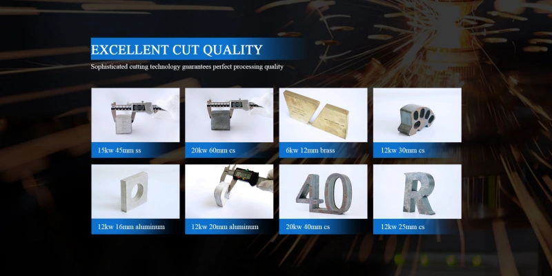
MAGICK’s cutting tests and quality control include real-material cutting and sample inspection before shipment. For a particular order, request records that connect that work to the proposed configuration and your part requirements. MAGICK
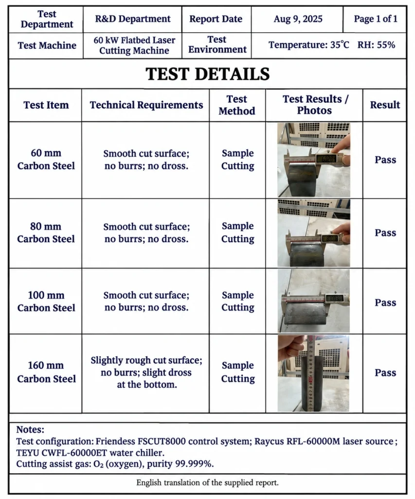
Once a trial meets the agreed criteria, save the approved combination. Record subsequent changes so operators can distinguish a known baseline from an experimental setting.
That makes the next repeat order easier to prepare and gives the team a useful starting point when a result changes.
12kW Fiber Laser Cutting Parameters FAQs
What Are the Starting Parameters for Cutting Stainless Steel with a 12kW Fiber Laser?
Choose the row that matches the thickness and reference configuration, then confirm the grade, head, nozzle, gas supply and finish requirement. The charts above provide selected reference entries. Validate the combination on your actual part before treating it as an approved production setting.
Why Does a 12kW Parameter Chart Sometimes Specify Less Than 12,000W?
Rated source power and commanded process power are different. The reference carbon-steel oxygen entries include settings below full output. Oxygen contributes reaction heat, and the process still needs an appropriate combination of speed, focus, nozzle and gas delivery. Full output is not automatically the correct setting for every operation.
Can I Use 12kW Cutting Parameters on a 6kW Machine?
Do not transfer the row unchanged or simply halve the speed. Start with the approved 6kW process reference for the relevant source, head, material and gas. A lower-power source needs its own suitable parameter combination and validation.
Why Do the Same Settings Give Different Results on Another Machine?
The displayed numbers may not describe equivalent conditions. Compare the source variant, optical configuration, focus calibration, nozzle, material and gas delivery. Confirm measurement references and units as well. A transferable record needs enough detail to explain what the numbers represent.
Get 12kW Settings That Match Your Production
If your team is spending too much time recovering from inconsistent cuts, bring the difficult part into the discussion.
Share the material grade, thickness, drawing, edge requirements, existing source and cutting-head details, and available gas supply. Explain where the current process loses time—during cutting, cleanup or assembly.
Explore the MAGICK 12kW fiber laser cutting machine to discuss a suitable equipment configuration, or discuss your 12kW cutting requirements with the MAGICK team.
The aim is a documented process that produces acceptable parts repeatedly, with a clear understanding of the work needed before they move to the next operation.