
A tube laser cutting machine should fit the orders your workshop needs to deliver. A furniture manufacturer processing thin square tubes has different priorities from a fabricator cutting long structural sections. Both need consistent parts, but their requirements for clamping, support, handling and laser power can be very different.
Start with your production mix, then compare machines against it. The six steps below explain how to narrow the choice, compare MAGICK configurations and verify performance before placing an order.
1. Define Your Tubes, Finished Parts and Production Volume
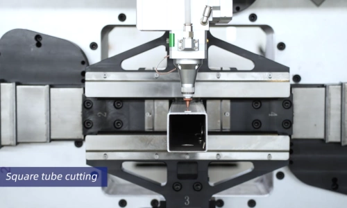
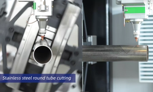
Prepare a short list of representative jobs: your most frequent order, your largest or heaviest tube, and your most demanding finished part. Record the material grade, profile dimensions, wall thickness, raw tube length, finished part length and required quantity for each.
Separate regular work from occasional requirements. A rare oversized job deserves a cost comparison with outsourcing before it determines the size of your entire machine.
| What to specify | Why it affects the purchase |
|---|---|
| Material grade and wall thickness | Establishes the cutting tests needed to select power and process settings |
| Round, square, rectangular or open profiles | Determines the clamping, support and centering requirements |
| Smallest and largest dimensions | Checks whether the machine covers the complete order mix |
| Raw tube length and weight | Determines the required working range and handling capacity |
| Longest finished part | Determines receiving, support and unloading requirements |
| Batch size and frequency of changeovers | Helps establish the appropriate automation level |
Check both ends of the size range. MAGICK’s brochure lists the MK-6012TY for round tubes of Ø10–120 mm and the MK-6024TY for Ø20–240 mm. The larger model does not automatically cover the smaller model’s full range. Ask for separate limits for square and rectangular tubes, together with any special jaws or fixtures.
Check raw tube length and finished part length separately. A machine accepting a 6.5 m raw tube does not automatically provide unloading for a finished part of the same length. Obtain the receiving-table layout and the supported finished-part dimensions.
Also distinguish chuck load capacity from the complete machine’s permissible workpiece load. Confirm the proposed tube’s total weight, weight distribution and support arrangement as one operating condition.
2. Choose the Chuck Arrangement and Machine Layout
Chuck count, bed layout and support design should be evaluated together. Each affects how the tube is held, moved and received during the cutting sequence.
A two-chuck machine is a practical starting point for conventional production. Consider it when the tube dimensions, finished lengths and handling requirements fit its configuration. For routine frame parts, brackets and repeat profiles, compare the complete cost of a suitable two-chuck setup before adding more equipment.
A three-chuck machine deserves closer consideration for long parts, heavier workpieces and demanding material handling. Depending on its arrangement, an additional chuck can support holding and transfer operations through more of the processing sequence. Suitable configurations also support zero-tail processing. Ask to see the complete cycle, including the last part and its unloading.
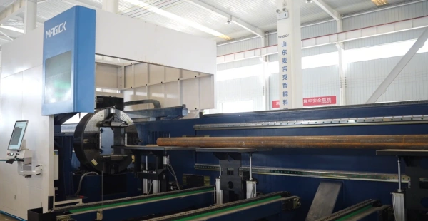
Horizontal and side-mounted layouts introduce another choice. Evaluate loading access, support positions, operator movement and the location of your material racks. For long or heavy tubes, review how the proposed setup supports the workpiece during rotation and transfer. The layout name alone does not establish its usable load capacity or finished-part accuracy.
Use the following table to form a shortlist from the MAGICK tube laser cutting machine range.
| Series | A useful starting point when… | Check before selecting |
|---|---|---|
| MK-TY | You need economical production of standard tubes and profiles | Minimum tube size, front-chuck overtravel, receiving arrangement and handling options |
| MK-T2W | You need a horizontal two-chuck system for a varied tube-processing workload | Exact size range, tube weight, support configuration and finished-part length |
| MK-T2C | A side-mounted two-chuck layout suits your material staging and loading workflow | Loader compatibility, operator access and the quoted support and unloading options |
| MK-T3W | Long or heavy workpieces make controlled support and receiving especially valuable | Chuck sequence, receiving length and zero-tail conditions for the selected configuration |
| MK-T3C | You need a side-mounted three-chuck system for long, heavy or large-diameter tubes | Profile capacity, loading layout and support through cutting and unloading |
These are starting points for selection. Compare the exact model and equipment package against your drawings before choosing a series.
3. Select Laser Power Using Representative Parts
Specify your common material and thickness first, then the most difficult work you expect to run regularly. A machine that completes one thick-wall demonstration still needs to meet your required cycle time and edge-quality standard in production.
Request sample cutting with the proposed power, cutting head and assist gas. Keep the material specification, drawing and acceptance criteria consistent when comparing options.
Evaluate the complete part: cut edges, corners, holes, mating surfaces and any preparation required before welding or assembly. Include a part with the small features or closely spaced holes that matter to your orders.
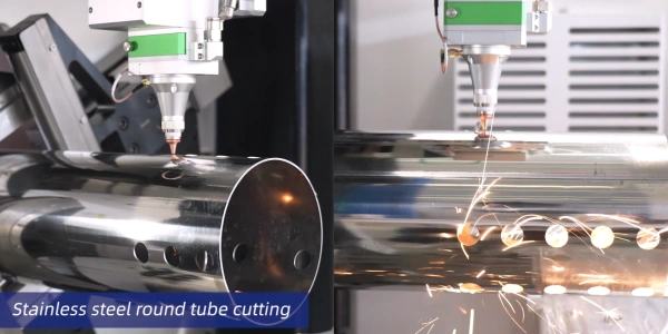
Keep travel speed separate from cutting performance. The maximum movement speed in a specification table is not a promise of cutting speed through your chosen wall thickness. Ask for the time required to produce an accepted part, with loading, positioning, cutting and unloading identified.
Compare additional power against the process it would improve. If cutting occupies most of the measured cycle, test whether a higher-power option provides worthwhile savings. If loading or part removal consumes most of the time, evaluate that constraint alongside power.
Bevel cutting also requires its own equipment and acceptance criteria. Specify the angle, wall thickness, edge condition and dimensional tolerance, then confirm the required cutting head, control functions and software are included in the quotation.
4. Match Loading and Unloading to Your Order Mix
Choose automation around the work your operators perform throughout a shift.
Manual loading can suit short batches, frequent changes and irregular jobs when suitable lifting equipment and staffing are available. Include the time needed to position, align and secure each tube in the comparison.
Semi-automatic loading is worth evaluating when repeat jobs justify assistance with staging and feeding material, while operators remain involved in the process. Establish exactly which steps the quoted system performs.
Fully automatic loading deserves consideration for repeat production with compatible tube sizes and predictable material supply. Check its supported shapes, minimum and maximum lengths, tube weights and changeover requirements using your actual stock.
An automatic loader and automatic feeding through the machine are different functions. A control-system feature list does not establish that the external loader, sensors and mechanical equipment are included.
Plan unloading at the same time. Check how short parts are collected, how long parts remain supported, and whether sorting or manual removal interrupts production. Tube-cutting equipment manufacturers also treat unloading as a separate part of the automation chain.
Review the full installation drawing with your workshop layout. Reserve space for tube bundles, finished parts, material movement and maintenance access, as well as the machine and its accessories.
5. Compare Tail Remnants and Cost per Accepted Part
A shorter tail remnant can improve material use, but compare it on the actual model and cutting job. MAGICK configurations have different remnant specifications; one two-chuck figure should not be applied to the entire range. Zero-tail capability likewise needs to be checked for the selected three-chuck arrangement and production conditions.
Ask the supplier to show how the final part is clamped, cut and unloaded. Record the tube profile, raw length, part layout and remaining material. Establish whether the stated remnant is a minimum achievable value or the result from your representative production test.
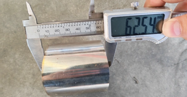
Two-Chuck – 62 mm Tail Remnant
Three-Chuck – Zero Tail Remnant
Suggested caption: Tail-remnant comparison for the identified MAGICK configurations. Include model names, tube dimensions, the part layout and measured remaining material.
Zero tail does not mean every millimetre of purchased stock becomes a saleable part. Cutting kerf, end trimming, part geometry and nesting can still affect yield. Review the number of accepted parts obtained from a full tube alongside the final remnant.
For illustration, reducing the remnant by 100 mm over 10,000 tubes represents 1,000 m of material length. This is a calculation example, not a MAGICK production result. Its financial value depends on tube weight per metre, purchase price, scrap recovery and whether the extra length produces usable parts.
A useful comparison is:
Cost per accepted part = Total batch production cost ÷ Number of accepted parts
Include material cost net of scrap recovery, gas, electricity, labor, consumables, post-processing and the machine costs allocated to the batch. Keep rejected pieces in the batch cost and divide by the accepted quantity.
Compare supplier trials using the same drawings, quantity and quality criteria. A higher purchase price needs a measurable benefit through usable output, reduced labor, lower rework or work that the alternative configuration cannot handle. Tail length is one part of that decision.
6. Verify the Configuration Before Placing an Order
Turn the agreed requirements into a written factory acceptance test, or FAT. Use your drawings and representative tube stock so the demonstration answers your production questions.
| Verification item | Evidence to request |
|---|---|
| Tube compatibility | Cutting of your specified material, dimensions and wall thickness |
| Handling and support | Demonstration with the agreed tube weight, raw length and finished-part length |
| Part quality | Measurements of critical holes, lengths, angles and mating features |
| Repeatability | Several consecutive accepted parts from the same setup |
| Productivity | Recorded cycle time with loading and unloading conditions stated |
| Material use | Nesting layout, accepted part count and measured tail remnant |
| Software and equipment | Exact controller, software edition, licenses, installed options and hardware list |
| Installation and support | Utility requirements, training scope, warranty coverage and service arrangements |
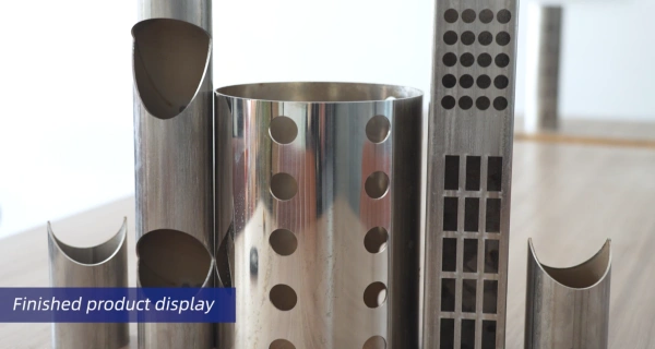
Distinguish positioning accuracy from finished-part tolerance. Check the dimensions that matter on the actual sample. A positioning specification alone does not establish the result on every material, profile and cutting process.
Software should be checked through an operating demonstration. Friendess describes TubePro as providing tube-centering compensation and cutting control, while TubesT handles tube nesting. Ask the supplier to import your drawing, prepare the layout and run the required functions on the quoted configuration. Confirm any limitations on profiles, nesting features or licensed options.
For welding preparation, request a sample that can be checked against the next operation. Verify fit-up and edge requirements before accepting a bevel or joint-cutting package.
Finally, obtain a complete quotation covering loading and receiving equipment, cutting head, software, cooling, extraction, installation and training. Separate included equipment from options, and agree on the final specification and acceptance criteria in writing.
Send MAGICK your tube specifications, representative drawings, longest finished-part length and target production volume. These details allow the proposed chuck arrangement, power and handling system to be evaluated against your actual work. Request a configuration proposal and sample-cutting evaluation before making the final selection.
